CDU Button Box for Citation CJ4 and MSFS
Overview
What is this project?
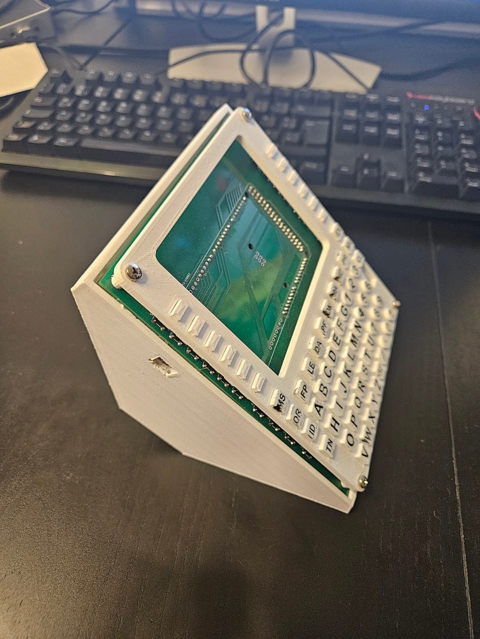
This is a physical recreation of the CDU in a Citation CJ4, for use with Microsoft Flight Simulator 2020. Although a simplified and stripped down version of it.
It has no screen, but all the important keys, their layout and function, have been kept. (The BRT and DIM keys are missing, but without a screen they wouldn't do anything anyway).
What's a "CDU"?
A "Control and Display Unit" is the primary interface between a pilot and the flight management system of an airplane.
The flight plan, approaches, frequencies, transponder codes, performance calculations and a whole lot of other things are done through the CDU.
Depending on the airplane, CDUs come in various shapes, sizes and layouts.
They all follow the basic "screen plus a bunch of buttons" style though.
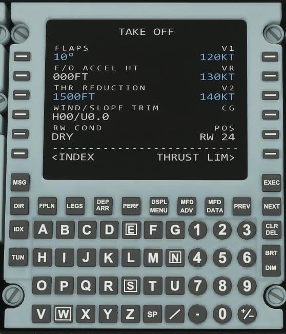
The CDU in this project is for a Citation CJ4 (in particular the Working Title CJ4 Mod for MSFS2020).
In the simulator it looks like this:
Why do I want one?
If you spend a lot of time flying virtual aircraft in a at least semi-serious manner, you will quickly find that a lot of time spend is interacting with the CDU.
Before taking off, you usually spend a couple minutes putting data into the CDU.
I already have a stick, throttle and rudder pedals. Why not also bring another thing I regularly use into the physical world?
Hardware
The CDU is constructed from a sandwich consisting of a 3D printed front plate, 3D printed keys, a PCB with buttons on it and an Arduino Mega.
Without the BRT and DIM Keys, there are 66 keys in total. Luckily, the Mega has just barely enough pins for every key.
Front plate
The front plate is just a simple flat plate, with cutouts for the various keys and four holes for screws to mount it to the PCB.
Keys
The keys are also 3D printed. They have a small lip on the back that keeps them from falling out the front. When assembled the PCB buttons hold them in from the back.
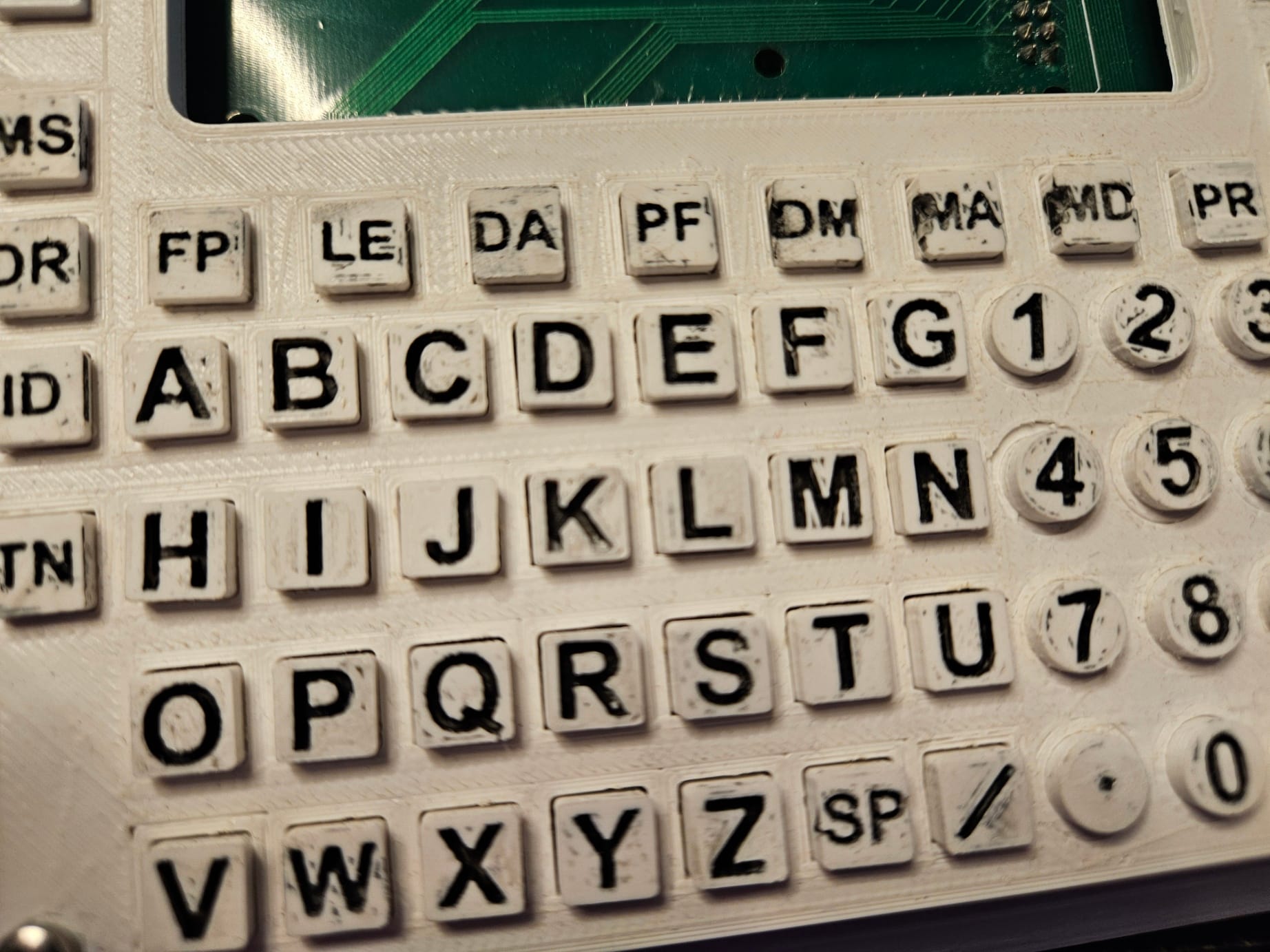
Painting the keys
To get the black text, each key has a deep recess.
Black acrylic paint is used, thinned with a lot of water. The paint is then liberally applied to the front of the key, until the recess is practically filled with black paint.
After drying, the front of the key is then sanded until all excess paint is removed, leaving only the recess painted black with a white front.
A couple things to note:
- The paint has to be really thin to get into the recesses. Use multiple coats to get a better black
- If the surface of the key has holes / cracks, you will end up with black in places you don't want it (you can see a lot of this on my keys)
PCB
The PCB is a simple, 2 layer board.
There are 66 buttons on it, each connected to GND and a pin on the Arduino.
The trouble with footprints
Unfortunately, the footprint I used for the button turned out to be different to the buttons I ordered.
Physically the buttons fit. But on the footprint I was using in KiCad the pins where internally connect vertical (Pins 2+4 and 1+3), while the real buttons where connect horizontally (Pins 1+2 and 3+4). On the PCB Pins 2 and 4 are connected to GND while Pin 3 is connected to the Arduino.
This meant all the Arduino Pins where connected to GND all the time, regardless of if the button was pressed or not.
In this state the PCB was unusable.
Fortunately, all the GND traces are on the back of the PCB.
I cut all of them and wired GND to every button by hand.
This worked and now the PCB was usable again.
Arduino Mega
The Arduino Mega was chosen for two reasons:
- It works well with the software I used
- It had just enough pins for every key on the keyboard
The PCB has pins sticking out the back, into which the Arduino simply plugs into.
To note:
- With the amount of pins plugging in at the same time, the friction becomes extremely high. It is very hard to plug the Arduino into the board, and even harder to remove it safely
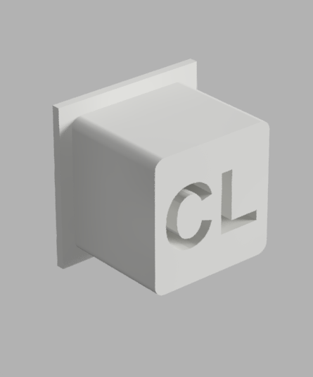
- If inserted fully, the metal USB port touches the pins of a couple buttons on the PCB. To prevent that I glued in a small plastic piece
Software
For some reason, not all inputs for aircraft are exposed in the keybind menu in MSFS. This applies to mods (such as the Working Title CJ4 mod I used) as well as stock aircraft.
For this project, none of the CDU buttons can be bound.
How ever, there is a solution.
Mobiflight is an open source project designed for building your own flight sim hardware.
More importantly for us, it has the ability to send the correct type of events of the CDU of the CJ4.
For that to work you need to install the WASM module (Mobiflight should ask you to do that on its own) and download the preset for the CJ4 from HubHop.
Both the configuration for the module (*.mfmc) and for the inputs (*.mcc) are available on my github at: https://github.com/wolff-jonas/cj4-cdu/tree/main/mobiflight
Retrospective
The good
It works! It is 100% usable for everything it is designed for, and I actually used it a lot while flying.
The sandwich construction also worked perfectly. Nothing moves that shouldn't, the keys move freely and feel good to press.
Assembly was easy, thanks to the PCB. Getting everything to line up perfectly on perfboard would have been a nightmare.
The text on the keys came out a lot better than I was expecting. I would definitely do it again this way. Just with a bit more care and better print settings.
It's robust and doesn't look like something someone made out of scrap they found. I had no problem handling it, there is really nothing that is prone to break off.
The bad
CHECK YOUR FOOTPRINTS!
Screwing up the button footprints was easily the biggest mistake on this project.
Luckily I could rework it and it only took me ~2 hours to fix it. The other option would have been to fix the footprints, redo the PCB routing and order another set of PCBs. Which would also probably take a couple hours, a bit of money and weeks of waiting.
Don't plug an Arduino Mega directly into a board.
Yes its sounds really easy and convenient. But the footprint is awkward to integrate into a PCB and ends up creating a lot of unusable space. Plugging all those pins in at the same time is also really hard. Removing it again is basically impossible without damaging something. The friction from 60+ pins really adds up.
It also causes issues with the USB port touching pins on the PCB, which can short them to ground.
So: use connector cables.
Take more time to make things pretty!
While it doesn't look bad, just taking a bit more time could have made it look a lot better.
Things like sanding the front plate, dialing in the print settings, being more careful painting and actually cleaning the PCB.
The "I would do this in the next version"
Connect the Arduino through cables, instead of directly into the PCB.
Better yet, use shift registers on the PCB to drastically reduce the number of pins needed.
That also leaves opportunity for more features, maybe even some outputs.
Add a screen.
The screen is 50% of the functionality of a real CDU, and including one would really make this project awesome.
Two major problems with that though: Finding one that fits the form factor, at least roughly. And finding a good way to connect it to MSFS.
Find a different way to put the text on the keys.
The current way looks okay and is easy to do. But the resolution is too low, I had to redo quite a few of the longer labels. Alternatively, use a 3D printer that achieves the needed resolution (maybe resin printing?)
Also add a anti-rotation feature to the number keys. They tend to rotate a bit.
Miscellaneous
For my dimensions I compromised between key size and desk space. It needs to fit between everything else I have on my desk for flight simming. I tried to preserve the proportions as best as I could, but the actual dimensions are definitely wrong.
Finding the actual dimensions of the real life CDU proved to be surprisingly impossible.
I searched for a long time, with no success. There where a few sales pitches and replacement parts online, but no actual datasheets.
But while writing this article I had the idea to check the WaybackMachine. And lo and behold! I managed to find a snapshot of Rockwell Collins website from 2008, with all the information about the FMS-3000 system.
The actual dimensions are 6.375 x 5.75 in (Height x Width) or 17 Dzus Units.